


Case 1: How leads determine direction
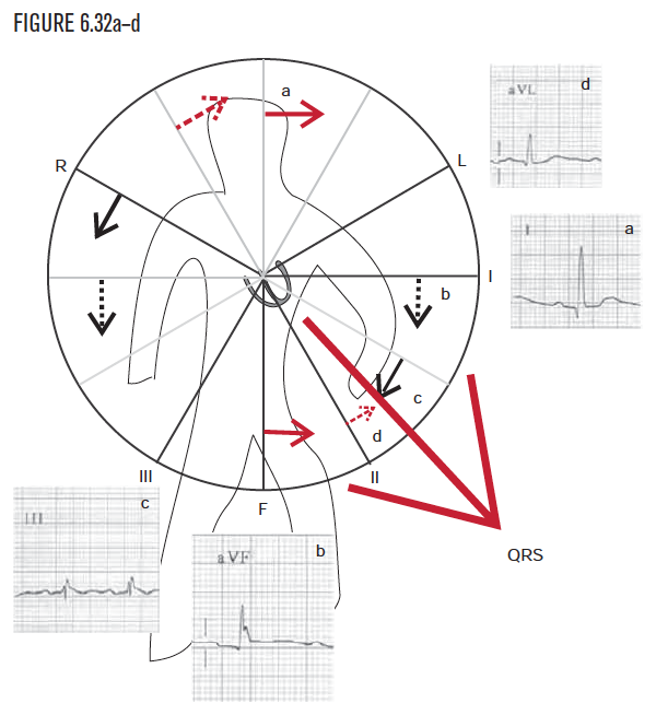
For this example, let’s visualize ventricular electrical systole, which is represented by the QRS. To determine and visualize whether the QRS is pointing, right or left, as well as up or down, first examine lead I. Because lead I is positive, the QRS is visualized as pointing toward the patient’s left. This is not yet a complete description or picture.
Because the QRS in lead I was positive, the QRS was visualized as pointing to the patient’s left side. To help complete the visualization, the observer needs to next determine whether the QRS force is toward the patient’s head or feet as well. The sensor that can distinguish up from down is called lead AVF. As lead AVF is positive, the observer visualizes the QRS as pointing toward the patient’s feet, that is, inferiorly. This can seem totally counterintuitive, so go over this page very carefully!
Although the information from leads I and AVF was drawn on separate diagrams for purposes of illustration, drawing them on one diagram helps construct a more complete visualization. Looking at leads I and AVF together will narrow the direction to one of the four quadrants. In this example, the QRS axis lies below line I and to the left of line AVF, or in the lower left quadrant. (Mathematically, the axis is greater than 0° and less than positive 90°.) Remember that (a) any electrical event (P wave, QRS, T wave, anything else!) that is above the baseline in lead I can be visualized as pointing to the patient’s left, and (b) any electrical event that is above the baseline in lead AVF is pointing toward the patient’s feet, that is, inferiorly (see Figure 6.63).
Using lead I and lead AVF will narrow down any force to one of the four quadrants on the diagram. In this example, because leads I and AVF are positive, the observer can visualize the QRS and ventricular depolarization as grossly pointing down and to the patient’s left. For greater accuracy, the axis can be narrowed down further to a multiple of 15°, as shown in Figure 6.25. To calculate the axis to multiples of 15°, additional information is needed from the other four one-dimensional sensors: leads II, III, AVR, and AVL. With the information from these leads, the observer can narrow the visualization down to one of the arrows.
To determine the exact direction inside a quadrant, the observer can look at a lead outside the quadrant. In this example, leads III, AVR, and AVL lie outside the lower left quadrant. Again, each of the 12 EKG leads is so primitive it can “see” only in one dimension and can sense only if an electrical force is coming toward it or going away from it. Lead III gives the observer the perspective from the patient’s lower right side.
Combine the directional information from the three leads (I, AVF, and III) into one diagram.
- Lead I is positive.
- Lead AVF is positive.
- Lead III is positive.
Using 1, 2, and 3, from above, the visualized direction is greater than +30° and less than +90°. Since we are using multiples of 15, the axis must be +45°, +60°, or +75°.
To narrow down the exact direction inside a quadrant, the observer can again look at a lead outside the quadrant. In this example, AVR and AVL lie outside the lower left quadrant. Again, each of the 12 EKG leads is so primitive it can “see” only in one dimension and can sense only if an electrical force is coming toward it or going away from it. Lead AVL offers the observer the perspective from the patient’s left shoulder.
Summary and conclusion—step by step
We have determined that:
| Lead | Which told us |
|---|---|
|
Lead I is positive |
the QRS direction is to the patient’s left side
|
|
Lead AVF is positive |
the QRS direction is to the patient’s feet |
|
Lead III is positive |
the QRS direction was >30° |
|
Lead AVL is positive |
the QRS direction was <60°, and so QED +45! |
And all that information is equivalent to saying the QRS direction is +45!
Case 2: Another example of normal
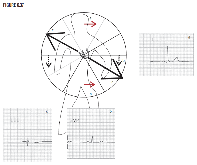
In this example, the QRS in lead I is positive, and so points to the patient’s left side. The QRS is positive in lead AVF (careful!). It so points toward the lead and, therefore, downward toward the patient’s feet (see Figure 6.63).
In this example, the positive QRS in lead I and positive QRS in lead AVF lets the observer visualize the direction as down and to the patient’s left side. (Mathematically, QRS direction is expressed as somewhere between 0° and 90°.) To narrow down the direction more precisely, look at another lead outside the lower left quadrant. Lead III or lead AVL would help. For this example, arbitrarily select lead III to examine first. The observer sees that the QRS in lead III is neither obviously positive or negative. This is called an isoelectric lead. When a lead is isoelectric, it provides a helpful and specific clue, because the true direction must be perpendicular to this lead.
Summary and conclusion—step by step
We have determined that:
| Lead | Which told us |
|---|---|
|
Lead I is positive |
the QRS direction is to the patient’s left side
|
|
Lead AVF is positive |
the QRS direction is to the patient’s feet |
|
Lead III is positive |
the QRS direction was either −150° or +30° |
And all that information is equivalent to just saying the QRS direction is +30! This is a normal QRS direction.
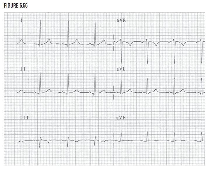
Case 3: Abnormal QRS direction in the frontal plane
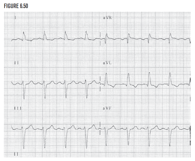
Begin at the beginning with lead I. In this example, the QRS in lead I is positive, so the QRS direction is to the patient’s left side. Mathematically, the QRS is somewhere between −90° and +90°.
Lead AVF is negative. This means the QRS direction is away from Lead AVF or upward. (Always be very careful thinking about lead AVF. It is very easy to make a careless mistake with this lead!) It is not normal for the QRS direction to be upward, so the observer needs to determine the direction more precisely. Although diagnostic possibilities include inferior infarction and left anterior hemiblock, do not worry about the diagnosis yet. These will be covered in depth in later chapters. Focus on learning to differentiate up from down and left from right (Figure 6.63)!
Combining the information from leads I and AVF, as was done in the previous examples, visualize the QRS direction to be leftward and upward.
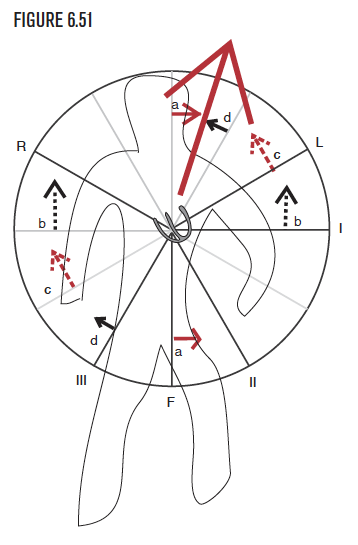
The positive QRS in lead I and negative QRS in lead AVF let the observer visualize the direction to the patient's left side and upward. Mathematically, the QRS direction is somewhere between 0° and −90°. To narrow down the direction more precisely, look at another lead outside the left upward quadrant. Lead II or lead AVR would help. For this example, arbitrarily examine lead II. The QRS in lead II is negative. Because lead II records the QRS as negative, the QRS is going away from lead II.
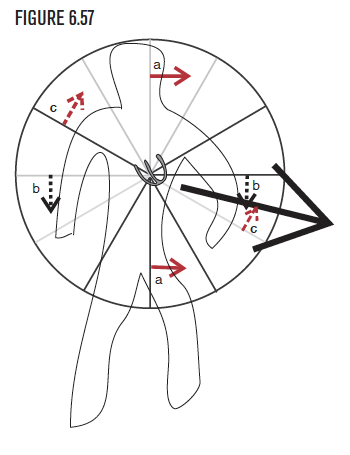
Now combine the information from lead II with the information from leads I and AVF onto one diagram.
- Using the information from lead I (a), the QRS direction is to the patient’s left side.
- Using the information from lead AVF (b), the QRS direction is upward, superiorly, to the patient’s head.
(Mathematically, the direction is visualized as between 0° and −90°.) Lead II is negative, thus the observer can visualize the QRS as also pointing away from lead II. Now the direction is visualized as somewhere between −30° and −90°. The direction can be determined even more precisely by looking at another lead outside the upper left quadrant, namely lead AVR.
To improve visualization, add information from another lead outside the upper left quadrant, namely lead AVR. In this example, lead AVR is slightly more positive than negative. Therefore the QRS direction is headed toward lead AVR.
Summary and conclusion—step by step
We have determined that:
| Lead | Which told us |
|---|---|
|
Lead I is positive |
the QRS direction is leftward |
|
Lead AVF is negative |
the QRS direction is upward or superiorly |
|
Lead II is negative |
the QRS direction was <−30° |
|
Lead AVR is positive |
the QRS direction was <−60°, and so must be −75°! |
And all that information is exactly equivalent to just saying the QRS direction is −75°! This QRS direction is abnormal.
Case 4: Use the frontal plane and the horizontal plane
The frontal plane—step by step
We have determined that:
| Lead | Which told us |
|---|---|
|
Lead I is positive |
the QRS direction is leftward |
|
Lead AVF is positive |
the QRS direction is downward or inferiorly |
|
Lead III is negative |
the QRS direction was <+30°, and so the direction is +15° |
And all that information is exactly equivalent to just saying the QRS direction is +15°! This QRS direction is normal.
Case 5: The P wave direction—Arm lead misplacement
Case 6: The P wave direction—Dextrocardia
Case 7: The P wave direction—Junctional rhythm
Image credits
Unless otherwise noted, images are from Adobe Stock.